5-4
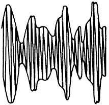
Figure 5-2.—Rf carrier amplitude-modulated by a complex wave envelope.
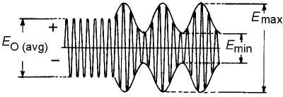
Since the preceding two modulation percentages often differ, you should define the AVERAGE
PERCENTAGE OF MODULATION, as shown below (refer to fig. 5-3):
Figure 5-3.—Rf amplitude percentage modulation wave envelope.
From the preceding definitions of percentage of modulation, you should note that methods of
measuring all three types of modulation percentages must be devised. When differing values are obtained,
however, the cause may not necessarily be directly related to unequal positive and negative peaks of a
complex modulation wave. Another possibility is distortion caused by carrier shift. Distortion may also be
produced by effects other than the modulation process — for example, parasitic oscillation, nonlinear
radio-frequency amplification of modulated signals, and distortion present in the audio amplifiers.
Unfortunately, continuous variations in the percentage of modulation create a number of additional
problems. For example, damping is necessary so that a meter can provide an average reading despite
fluctuations. An average reading, on the other hand, will not disclose the presence of transient
overmodulation. This shortcoming is serious because of the large number of sideband frequencies
produced in addition to the normal ones whenever overmodulation occurs. Not only do these extra
frequencies interfere drastically with other transmissions, but they also may significantly distort the
modulation signal. These considerations account for the importance of using a meter that responds to


