2-4
The meter (M301) contains four scales. The upper scale is graduated from 0 to 100 for direct
numerical readings. The three lower scales, numbered 1, 2, and 3, are read for LEAKAGE, QUALITY,
and GAS, respectively. Each numbered scale includes green and red areas marked GOOD and
REPLACE. Inside a shield directly in front of the meter are five neon lamps (DS301 through DS305),
which indicate shorts between tube elements.
The number 2 pushbutton (MP6) is used for transconductance, emission, and other quality tests
(described later). The number 3 pushbutton (MP7) is used to test for the presence of gas in the tube
envelope. The number 4 pushbutton (MP8) is used for tests on dual tubes. A neon lamp (DS203) lights
when pushbutton number 4 is to be used. Eleven tube test sockets are located on the panel, plus tube pin
straighteners for the 7- and 9-pin miniature tubes.
The power ON-OFF spring-return toggle switch (S105) turns the tester on by energizing a line relay.
The pilot light (DS107) lights when this relay closes. Above the power ON-OFF switch are five fuses.
Fuses F101, F201, and F202 protect circuits in the tester not protected by other means and have neon
lamps to indicate when they have blown. Fuses F102 and F103 protect both sides of the power line.
Auxiliary Compartment
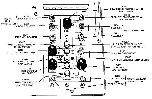
A group of auxiliary controls covered by a hinged panel is used for special tests and for calibration
of the tester. Two of these controls, labeled SIGNAL CAL (R152 and R155, fig. 2-2), are used with
special test cards for adjusting the regulation and amplitude of the signal voltage. A pushbutton labeled
CATH ACT (S302D) is used for making cathode activity tests. When this button is pressed, DS106 on the
front panel (fig. 2-1) lights, and the filament voltage of the tube under test is reduced by 10%. Results of
the test are read as a change in reading on the numerical meter scale.
Figure 2-2.—Auxiliary compartment.


