1-12
The antennas of most radar systems are designed to radiate energy in a one-directional lobe or beam that
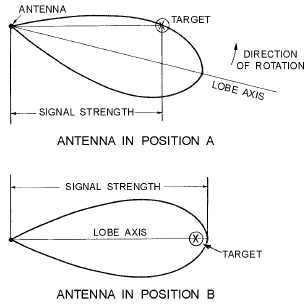
can be moved in bearing simply by moving the antenna. As you can see in figure 1-9, the shape of the
beam is such that the echo signal strength varies in amplitude as the antenna beam moves across the
target. At antenna position A, the echo is minimal; at position B, where the beam axis is pointing directly
at the target, the echo strength is maximum. Thus, the bearing angle of the target can be obtained by
moving the antenna to the position at which the echo is strongest. In actual practice, search radar antennas
move continuously; the point of maximum echo return is determined by the detection circuitry as the
beam passes the target or visually by the operator. Weapons-control and guidance radar systems are
positioned to the point of maximum signal return and maintained at that position either manually or by
automatic tracking circuits.
Figure 1-9.—Determination of bearing.
ALTITUDE
Many radar systems are designed to determine only the range and bearing of an object. Such radar
systems are called TWO-DIMENSIONAL (2D) radars. In most cases these systems are further described
as SEARCH RADAR SYSTEMS and function as early-warning devices that search a fixed volume of
space. The range and bearing coordinates provide enough information to place the target in a general area
with respect to the radar site and to determine distance, direction of travel, and relative speed. However,
when action must be taken against an airborne target, altitude must be known as well. A search radar
system that detects altitude as well as range and bearing is called a THREE-DIMENSIONAL (3D) radar.
Altitude- or height-finding search radars use a beam that is very narrow in the vertical plane. The
beam is scanned in elevation, either mechanically or electronically, to pinpoint targets. Height-finding
radar systems that also determine bearing must have a beam that is very narrow in both the vertical and
horizontal planes. An electronic elevation-scanning pattern for a search radar set is illustrated in figure 1-10.
Lines originating at the antenna indicate the number of beam positions required for complete elevation
coverage. In practice the beams overlap slightly to prevent any gaps in the coverage. Each beam position
corresponds to a slight change in either the frequency or phase of the radiated energy. A change in either
phase or frequency of the energy causes it to leave the antenna at a different angle. Thus, the frequency or


