4-18
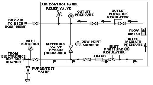
Figure 4-13.—Air control panel flow diagram.
The dew point (related to moisture content) and the flow of the lp dry air can be monitored at the air
control panel. Also, the dry-air pressure can be monitored at the input to the control panel, at the input to
the flowmeter (in which accuracy is calibrated at a certain pressure), and at the output of the control
panel. A filter is installed to trap particles that affect proper pressure regulation. A metering valve bypass
and a pressure relief valve are provided in case of malfunctions. The metering valve bypass permits
manual control of air pressure to the user equipment.
Electronic Equipment Dehydrators.
Dehydrators or compressor-dehydrators are supplied as part of various radars. Many of them were
provided prior to installation of properly configured central dry-air systems. These dehydrators are
intended for emergency use in the event of the failure of the central dry-air system. In a typical
configuration (figure 4-14), the outlet air from the local dehydrator is connected between the air control
panel outlet and the user equipment or radar by a three-way valve.


