3-16
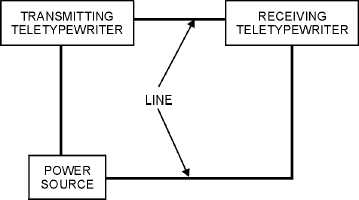
Figure 3-17.—Simple teletypewriter circuit.
If a teletypewriter signal could be drawn on paper, it would resemble figure 3-18. This is the code
combination for the letter R. Shaded areas show intervals during which the circuit is closed, and the blank
areas show the intervals during which the circuit is open. The signal has a total of seven units. Five of
these are numbered and are called INTELLIGENCE units. The first and last units of the signal are labeled
START and STOP. They are named after their functions: the first starts the signal, and the last stops it.
These are a part of every teletypewriter code signal: the START unit is always spacing, and the STOP
unit is always marking.
Figure 3-18.—Mark and space signals.
The teletypewriter signal is theoretically a perfect signal. The time between each unit remains the
same during transmission of the signal. The shift from mark to space (and vice versa) is called a
TRANSITION. A transition occurs at the beginning and end of each unit when it shifts from mark to
space or space to mark; a character may have two, four, or six transitions.
When figuring the time duration of a signal character, no allowance for transition time is made since
the transition is instantaneous and is considered to have zero time duration. The time duration for each
unit is measured in milliseconds.
Q10. What is the function of an antenna patch panel?
Q11. What are the functions of a multicoupler?
Q12. What are the terms used to describe an open or closed telegraph circuit?
Q13. How many units are in a tty signal and what are they?


