6-7
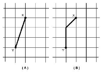
If the amount of deflection from the left and down occurred so that each set of plates acted at the
same time, the picture would be like the one in view A of figure 6-9. For example, if the vertical plates
moved the beam downward (starting from point X) at the rate of 3 units per second and the horizontal
plates moved it to the left at the rate of 1 unit per second, both movements would have been completed in
1 second at point Y. The result would be a straight line.
Figure 6-9.—Deflection of the beam.
In view B, the potentials on the vertical and horizontal plates change at the same rate. In the same
time period, say 1 second, both plates move the beam 1 unit. The horizontal plates have completed their
task at the end of 1 second, but the vertical plates have moved the beam only one-third of the required
distance. In this case, the picture in view B would appear on the screen.
Beam-deflection Plate Action
Recall from your study of chapter 2 of this module that waveforms are described in terms of
amplitude versus time. You have just seen how the movement of the CRT beam depends on both
potential (amplitude) and time.
Q-9. Waveforms are described in terms of what two functions?
VERTICAL-DEFLECTION PLATES.—We will use figure 6-10 to explain the action of the
vertical-deflection plates in signal amplitude measurements. As this discussion begins, remember that
vertical-deflection plates are used to show amplitude of a signal, and horizontal-deflection plates are used
to show time and/or frequency relationships.


