1-25
Similarly, the following resistance ratio exists between the four arms of the bridge, just as in the
resistance bridge expression discussed earlier:
or
Thus, both the unknown resistance and capacitance, R
x
and Cx, can be estimated in terms of known
resistance R1, R2, Rs, and known capacitance Cs.
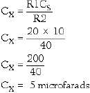
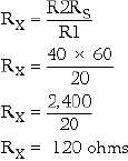
In figure 1-7, for example, we know that R1 is 20 ohms, R2 is 40 ohms, Rs is 60 ohms, and Cs is 10
microfarads. We can find the values of Cx and Rx by using the respective formulas as follows:
and
Q-19. When a bridge is used to measure resistance, what is the value of Rx if R1 equals 80 ohms, R2
equals 120 ohms, and R3 equals 280 ohms?
INDUCTANCE BRIDGE.—The value of the unknown inductance Lx may be determined by means
of the simple bridge circuit shown in figure 1-8. Ratio arms R1 and R2 are accurately calibrated resistors.
Ls is a standard inductor with a known inductance; Rs is the known resistance, and Rx represents the
resistance of the unknown inductor.


