4-20
Two of the most important parameters used for transistor testing are the transistor CURRENT GAIN
(BETA) and the COLLECTOR LEAKAGE or REVERSE CURRENT (ICO). Two other tests that can be
accomplished include the electrode resistance and diode measurements. You may want to review NEETS,
Module 7, Introduction to Solid-State Devices and Power Supplies, for a review of transistors before
continuing this section.
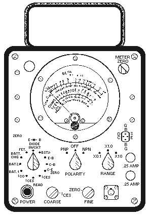
The Semiconductor Test Set AN/USM-206A (figure 4-17) is a rugged, field-type tester designed to
test transistors and semiconductor diodes. The set will measure the beta of a transistor, the resistance
appearing at the electrodes, and the reverse current of a transistor or semiconductor diode. It will also
measure a shorted or open condition of a diode, the forward transconductance of a field-effect transistor,
and the condition of its own batteries.
Figure 4-17.—Semiconductor test set.
To assure that accurate and useful information is gained from the transistor tester, you should make
the following preliminary checks of the tester before testing any transistors:
1. With the POLARITY switch in the OFF position, the meter pointer should indicate exactly zero.
(When required, rotate the meter ZERO ADJUST KNOB on the front of the meter to fulfill this
requirement.) To prevent battery drain, be sure to leave the POLARITY switch in the OFF
position when measurements are not actually being made.
2. Always check the condition of the test set batteries. To make this check, disconnect the test set
power cord, place the polarity switch in the PNP position, and place the function switch first to
BAT. 1and then to BAT. 2. In both BAT positions, the meter pointer should move so as to
indicate within the red BAT box.


