3-19
After you have adjusted the ohmmeter for zero reading, it is ready to be connected to a circuit to
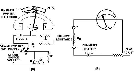
measure resistance. A typical circuit and ohmmeter arrangement is shown in figure 3-13. You must
ensure that the power switch of the circuit to be measured is in the de-energized (OFF) position. This
prevents the source voltage of the circuit from being applied to the meter, a condition that could cause
severe damage to the meter movement.
Figure 3-13.—Measuring circuit resistance with an ohmmeter.
Remember that the ohmmeter is an open circuit when the test leads are separated. To take a
resistance reading with a meter, you must provide a path for current flow produced by the meter’s battery.
In view A of figure 3-13, the meter is connected at points A and B to produce this path. Connecting these
test leads places resistors R1 and R2 in series with the resistance of the meter coil, the zero-adjust
potentiometer, and the series multiplying resistor. Since you previously calibrated the meter, the amount
of coil movement now depends only on the resistances of R1 and R2.
The addition of R1 and R2 into the meter circuit raises the total series resistance and decreases the
current. This decreases the amount of pointer deflection. The pointer comes to rest at a scale reading that
indicates the combined resistance of R1 and R2. If you were to replace either R1 or R2, or both, with a
resistor having a larger ohmic value, the current flow in the moving coil of the meter would be decreased
even more. This would further decrease the pointer deflection, and the scale indication would read a still
higher circuit resistance. View B is a simplified version of the circuitry in view A.
From our ohmmeter discussion, two facts should be apparent: (1) Movement of the moving coil is
proportional to the amount of current flow, and (2) the scale reading of the ohmmeter is inversely
proportional to current flow in the moving coil.
The amount of circuit resistance to be measured may vary over a wide range. In some cases, it may
only be a few ohms; in other cases, it may be as great as 1 megohm. Scale multiplication features are built
into most ohmmeters so that they will indicate any ohmic value being measured and offer the least
amount of error. Most ohmmeters are equipped with a selector switch for selecting the multiplication
scale desired. For example, view A of figure 3-14 shows a typical meter that has a six-position switch.
The positions are marked on the meter in multiples of 10, from R 1 through R 100K.


