15
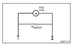
Figure 2A.—Shunt ammeter.
IN ANSWERING QUESTIONS 2-16
THROUGH 2-19, REFER TO FIGURE 2A.
THE METER IN THE CIRCUIT IS
DESIGNED FOR MAXIMUM OF .001
AMPERE AND HAS AN INTERNAL
RESISTANCE OF 10 OHMS. YOU ARE
FIGURING THE SHUNT RESISTANCE
NECESSARY TO MEASURE 5 AMPERES.
2-16. What is the voltage drop across the meter
coil?
1. .01 volt
2. .005 volt
3. .0001 volt
4. .0005 volt
2-17. What is the voltage drop across the shunt
resistance?
1. .01 volt
2. .005 volt
3. .0001 volt
4. .0005 volt
2-18. When the meter is deflected full scale
and is measuring 5 amperes, what is the
maximum value of current flow through
the shunt resistance?
1. 0.010 ampere
2. 0.490 ampere
3. 4.999 ampere
4. 5 amperes
2-19. What is the approximate value of the
shunt resistance?
1. .001 ohm
2. .002 ohm
3. .003 ohm
4. .004 ohm
2-20. Simple range-switching arrangements for
current meters are less satisfactory than
other methods of range switching for
which of the following reasons?
1. Meter damage can occur when line
current momentarily flows through
the meter
2. Resistance in the contacts may cause
inaccurate readings
3. Both 1 and 2 above
4. Resistor damage may occur
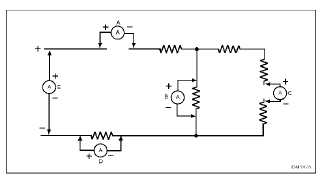
Figure 2B.—Ammeter connections.
IN ANSWERING QUESTION 2-21, REFER
TO FIGURE 2B.
2-21. In the figure, five ammeters are
connected to the circuit resistors. Of
those five, which one(s) is/are connected
correctly?
1. E only
2. A and E
3. A and C
4. A, B, and D


