2-11
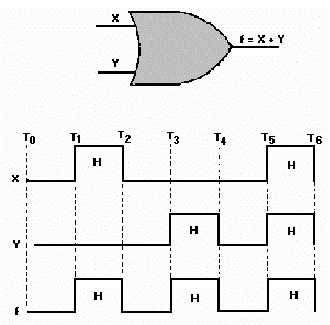
also goes HIGH and remains HIGH
until both inputs are again LOW. At T5,
both X and Y go HIGH
causing f to go HIGH.
Figure 2-8. OR gate input and output signals.
TRUTH TABLE
Using the inputs X and Y, lets
construct a Truth Table for the OR gate. You can see from the
discussion of figure 2-8 that there
are four combinations of inputs. List each of these combinations of
inputs and the respective outputs
and you have the Truth Table for the OR gate.
X Y
f 0
0
0 0
1 1
1 0
1 1
1
1 f = X + Y
When writing or stating the Boolean
expression for an OR gate with more than two inputs, simply
place the OR sign (+) between each
input and read or state the sign as OR. For example, the Boolean
expression for an OR gate with the
inputs of A, B, C, and D would be:
f = A+B+C+D
This expression is spoken "f equals A OR B OR C OR D."
You can substitute the complements
for the original statements as we did with the AND gate or use
negative logic; but for an output
from an OR gate, at least one of the inputs must be TRUE.

