1-5
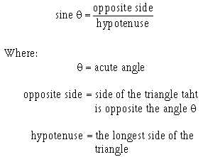
You should recall that the trigonometric ratio (inset in figure 1-3) for the sine in a right triangle (a
triangle in which one angle is 90 degrees) is:
When an alternating waveform is generated, the coil is represented by a vector which has a length
that is equal to the maximum output voltage (Emax). The output voltage at any given angle can be found by
applying the above trigonometric function. Because the output voltage is in direct relationship with the
sine of the angle !, it is commonly called a sine wave.
You can see this relationship more clearly in figure 1-3 where the coil positions in relation to time
are represented by the numbers 0 through 12. The corresponding angular displacements, shown as !, are
shown along the horizontal time axis. The induced voltages (V1 through V12) are plotted along this axis.
Connecting the induced voltage points, shown in the figure, forms a sine-wave pattern. This relationship
can be proven by taking any coil position and applying the trigonometric function to an equivalent right
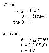
triangle. When the vector is placed horizontally (position 0), the angle ! is 0 degrees. Since e = Emax sine
!, and the sine of 0 degrees is 0, the output voltage is 0 volts, as shown below:


