3-35
In waveform (4), the incident wave is at a maximum negative value at the end of the line. The wave
has moved another 45 degrees to the right from the wave in the preceding illustration. The reflected wave
has also moved 45 degrees, but to the left. The reflected wave is in phase with the incident wave. The
resultant of these two waves, shown by the dark line, again has a negative maximum at the end of the line
DQG D SRVLWLYH PD[LPXP IURP WKH HQG RI WKH OLQH 1RWLFH WKDW WKHVH PD[LPD KDYH a greater amplitude
than those in waveform (3).
In waveform (5), the incident wave has moved another 45 degrees to the right and the reflected wave
GHJUHHV WR WKH OHIW 7KH UHVXOWDQW DJDLQ LV PD[LPXP QHJDWLYH DW WKH HQG DQG SRVLWLYH PD[LPXP
from the end. The maxima are lower than those in waveform (4). In waveform (6), the incident and
UHIOHFWHG ZDYH KDYH PRYHG DQRWKHU 7KH WZR ZDYHV DJDLQ DUH GHJUHHV RXW RI SKDVH JLYLQJ D
resultant wave with no amplitude. The incident and reflected waves continue moving in opposite
directions, adding to produce the resultant waveshapes shown in waveforms (7) and (8). Notice that the
PD[LPXP YROWDJH LQ HDFK UHVXOWDQW ZDYH LV DW WKH HQG DQG IURP WKH HQG
Study each part of figure 3-27 carefully and you will get a clear picture of how the resultant
waveforms of voltage are produced. You will also see that the resultant voltage wave on an open-ended
OLQH LV DOZD\V ]HUR DW DQG IURP WKH HQG RI WKH WUDQVPLVVLRQ OLQH 6LQFH WKH ]HUR DQG PD[LPXP
points are always in the same place, the resultant of the incident and the reflected wave is called a
STANDING WAVE of voltage.
The right-hand column in figure 3-27 shows the current waveshapes on the open-ended line. Since
the current is reflected out of phase at an open end, the resultant waveshapes differ from those for voltage.
The two out-of-phase components always cancel at the end of the transmission line, so the resultant is
always zero at that point. If you check all the resultant waveshapes shown in the right-hand column of
ILJXUH \RX ZLOO VHH WKDW D ]HUR SRLQW DOZD\V RFFXUV DW WKH HQG DQG DW D SRLQW IURP WKH HQG
0D[LPXP YROWDJHV RFFXU DQG IURP WKH HQG
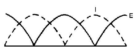
When an ac meter is used to measure the voltages and currents along a line, the polarity is not
indicated. If you plot all the current and voltage readings along the length of the line, you will get curves
like the ones shown in figure 3-28. Notice that all are positive. These curves are the conventional method
of showing current and voltage standing waves on rf lines.
Figure 3-28.—Conventional picture of standing waves.
When an rf line is terminated in a short circuit, reflection is complete, but the effect on voltage and
current differs from that in an open-ended line. Voltage is reflected in opposite phase, while current is
reflected in phase. Again refer to the series of pictures shown in figure 3-27. However, this time the left
column represents current, since it shows reflection in phase; and the right column of pictures now
represents the voltage changes on the shorted line, since it shows reflection out of phase.


