3-39
UNIJUNCTION SAWTOOTH GENERATOR.—So far, you have learned in this chapter that a
switch and an RC network can generate a sawtooth waveform. When using a unijunction transistor as the
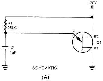
switch, a simple sawtooth generator looks like the circuit in figure 3-44, view (A); the output waveshapes
are shown in view (B). You may want to review unijunction transistors in NEETS, Module 7,
Introduction to Solid-State Devices and Power Supplies, chapter 3, before continuing.
Figure 3-44A.—Unijunction sawtooth generator. SCHEMATIC.
When the 20 volts is applied across B2 and B1, the n-type bar acts as a voltage- divider. A voltage of
12.8 volts appears at a point near the emitter. At the first instant, C1 has no voltage across it, so the output
of the circuit, which is taken across the capacitor (C1), is equal to 0 volts. (The voltage across C1 is also
the voltage that is applied to the emitter of the unijunction.) The unijunction is now reverse biased. After
T0, C1 begins to charge toward 20 volts.
At T1, the voltage across the capacitor (the voltage on the emitter) has reached approximately 12.8
volts. This is the peak point for the unijunction, and it now becomes forward biased. With the emitter
forward biased, the impedance between the emitter and B1 is just a few ohms. This is similar to placing a
short across the capacitor. The capacitor discharges very rapidly through the low resistance of B1 to E.
As C1 discharges, the voltage from the emitter to B1 also decreases. Q1 will continue to be forward
biased as long as the voltage across C1 is larger than the valley point of the unijunction.
At T2 the 3-volt valley point of the unijunction has been reached. The emitter now becomes reverse
biased and the impedance from the emitter to B1 returns to a high value. Immediately after T2, Q1 is
reverse biased and the capacitor has a charge of approximately 3 volts. C1 now starts to charge toward 20
volts as it did originally (just after T0). This is shown from T2 to T3 in figure 3-44, view (B).


