3-19
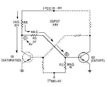
Figure 3-21.—Flip-flop (Q2 voltage divider).
With Q1 saturated, a large current flows through R5. The meter would measure approximately 0
volts (ground potential) at point (C). Notice that point (B) is located between point (C) (at 0 volts) and
+V
BB
(at +6 volts). The meter would measure a positive voltage (between 0 volts and +6 volts) at the base
of Q2 (point (B)).
A positive voltage on the base of a pnp transistor will cause that transistor to cut off. If one transistor
is saturated, the other must be cut off. The flip-flop is stable in this state.
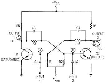
The capacitors that were removed from figure 3-19 must be returned to the flip-flop as shown in
figure 3-22 to change the state of the flip-flop from one condition to the other. Capacitors C3 and C4
transmit almost instantaneously any changes in voltage from the collector of one transistor to the base of
the other. Capacitors C1 and C2 are input coupling capacitors.
Figure 3-22.—Flip-flop.


