2-25
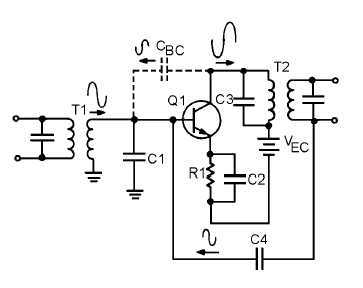
Figure 2-18.—Neutralized rf amplifier.
In figure 2-18, a feedback capacitor (C4) has been added to neutralize the amplifier. This solves the
problem of unwanted degenerative feedback. Except for capacitor C4, this circuit is identical to the circuit
shown in figure 2-17. (When CBC causes regenerative feedback, C4 will still neutralize the amplifier. This
is true because C4 always provides a feedback signal which is 180 degrees out of phase with the feedback
signal caused by CBC.)
Q-25.
What is the most common form of coupling for an rf amplifier?
Q-26.
What are two advantages of this type of coupling?
Q-27.
If current gain is required from an rf amplifier, what type of component should be used as an
output coupling element?
Q-28.
What problem is caused in an rf amplifier by a loosely coupled transformer?
Q-29.
How is this problem corrected?
Q-30.
What problem is caused by overcoupling in a transformer?
Q-31.
What method provides the widest bandpass?
Q-32.
What two methods are used to compensate for the problems that cause low gain in an rf amplifier?
Q-33.
What type of feedback is usually caused by the base-to-collector interelectrode capacitance?
Q-34.
How is this compensated for?
TYPICAL RF AMPLIFIER CIRCUITS
As a technician, you will see many different rf amplifiers in many different pieces of equipment. The
particular circuit configuration used for an rf amplifier will depend upon how that amplifier is used. In the
final part of this chapter, you will be shown some typical rf amplifier circuits.


