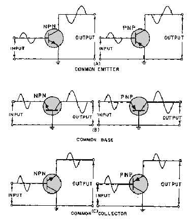
2-24
Figure 2-16.—Transistor configurations.
Each configuration, as you will see later, has particular characteristics that make it suitable for
specific applications. An easy way to identify a specific transistor configuration is to follow three simple
steps:
1. Identify the element (emitter, base, or collector) to which the input signal is applied.
2. Identify the element (emitter, base, or collector) from which the output signal is taken.
3. The remaining element is the common element, and gives the configuration its name.
Therefore, by applying these three simple steps to the circuit in figure 2-12, we can conclude that this
circuit is more than just a basic transistor amplifier. It is a common-emitter amplifier.
Common Emitter
The common-emitter configuration (CE) shown in figure 2-16 view A is the arrangement most
frequently used in practical amplifier circuits, since it provides good voltage, current, and power gain.
The common emitter also has a somewhat low input resistance (500 ohms-1500 ohms), because the input
is applied to the forward-biased junction, and a moderately high output resistance (30 kilohms-50 kilohms
or more), because the output is taken off the reverse-biased junction. Since the input signal is applied to
the base-emitter circuit and the output is taken from the collector-emitter circuit, the emitter is the element
common to both input and output.


