2-17
not. In most applications in electronics, this method is not used because it is not as efficient as thermionic
emission. There are two applications where cold-cathode emission is used. The first application you are
already familiar with, although you may not be aware of it. Every time you look at a neon sign you are
watching a cold-cathode tube in operation. Thus, the first application of cold-cathode tubes is for visual
display. You are also familiar with the reason for this visual display. In the NEETS module on matter and
energy, we explained that when energy is fed into an atom (neon in this case), electrons are moved, or
promoted, to higher orbits. When they fall back, they release the energy that originally lifted them to their
higher orbits. The energy is in the form of light. Cold-cathode tubes are also used as VOLTAGE
REGULATORS. Because voltage regulators will be dealt with extensively in the next chapter, we will
not cover their operation now. At this point, you only need to understand that a cold-cathode tube has the
ability to maintain a constant voltage drop across the tube despite changes of current flow through the
tube. The tube does this by changing resistance as current flow varies.
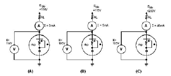
Examine figure 2-16. Here you see a cold-cathode tube connected to a variable voltage source. The
variable resistor rkp does not exist as a physical component, but is used to represent the resistance
between the cathode and the plate. Most cold-cathode tubes have a firing point (ionizing voltage) at about
115 volts. Thus, the tube in view A of the figure is below the firing point. Because the tube lacks
thermionic emission capabilities, no current will flow and the tube will have a resistance (rkp) near
infinity. The potential difference between the plate and ground under these conditions will be equal to the
source (Ebb) voltage, as shown on the voltmeter.
Figure 2-16.—Cold-cathode tube operation.
In view B, the source voltage has been raised to the firing point of 115 volts. This causes the gas to
ionize and 5 milliamperes of current will flow through the tube. Because the tube represents a resistance
(rkp), voltage will be dropped across the tube; in this case, 105 volts. The plate-load resistor (RL) will
drop the remaining 10 volts. The resistance of the tube at this time will be equal to:


