1-5
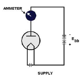
The path of the second series circuit is from one side of the filament, across the space to the plate,
through the ammeter and battery, then back to the filament. This circuit is known as the plate circuit.
You will note that a part of the filament circuit is also common to the plate circuit. This part enables
the electrons boiled from the filament to return to the filament. No electron could flow anywhere if this
return path were not completed. The electron flow measured by the ammeter is known as plate current.
The voltage applied between the filament and plate is known as plate voltage. You will become
familiar with these terms and with others that are commonly used with diodes and diode circuits as we
progress.
Diode Operation with a Positive Plate
Fleming started with a two-element tube (diode) similar to Edison’s and at first duplicated Edison’s
experiment. The results are worth repeating here. Look at figure 1-3 again.
With the plate POSITIVE relative to the filament, the filament hot, and the circuit completed as
shown, the ammeter detected a current flowing in the plate circuit. Because current is the same in all parts
of a series circuit, we know that the same current must flow across the space between filament and plate.
We know now that the electrons boiled from the heated filament are NEGATIVE and are attracted to the
POSITIVE plate because UNLIKE CHARGES ATTRACT.
Diode Operation with a Negative Plate
Fleming’s next step was to use a similar circuit but to reverse the plate battery. The circuit is shown
in figure 1-4.
Figure 1-4.—Diode with a negative plate.
With the plate NEGATIVE relative to the filament, the filament hot, and the circuit completed as
shown, the ammeter indicated that ZERO current was flowing in the plate circuit.
Fleming found that the NEGATIVE charge on the plate, relative to the filament, CUT OFF the flow
of plate current as effectively as if a VALVE were used to stop the flow of water in a pipe.


