19
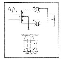
Figure 3A.
Complete full-wave rectifier.
IN ANSWERING QUESTIONS 3-19 AND
3-20, REFER TO FIGURE 3A. ASSUME
THAT THE VOLTAGE ACROSS THE
TRANSFORMER SECONDARY HAS AN
RMS VALUE OF 240 VOLTS AC.
3-19.
What is the peak value of the voltage
pulses across the load?
1. 339.4 volts
2. 239.8 volts
3. 169.7 volts
4. 76.3 volts
3-20.
What is the average output voltage?
1. 237.5 volts
2. 169.7 volts
3. 152.3 volts
4. 108.1 volts
THIS SPACE LEFT BLANK
INTENTIONALLY.
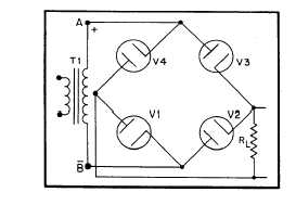
Figure 3B.
Bridge rectifier.
IN ANSWERING QUESTIONS 3-21 AND
3-22, REFER TO FIGURE 3B.
3-21.
When the voltage across the secondary
of the transformer has the polarity
shown, which of the diodes will
conduct?
1. V1 and V3
2. V2 and V4
3. V1 and V2
4. V3 and V4
3-22.
When the polarity reverses, which of
the diodes will conduct?
1. V3 and V1
2. V4 and V2
3. V2 and V1
4. V4 and V3
3-23.
In filter circuits, inductors are used as
what kind of impedances?
1. Shunt impedances to oppose
changes in current
2. Shunt impedances to oppose
changes in voltage
3. Series impedances to oppose
changes in current
4. Series impedances to oppose
changes in voltage