1-4
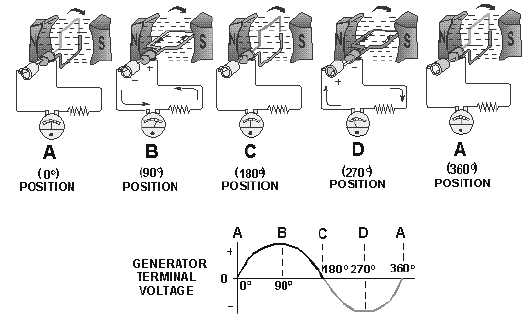
shown from points A, B, and C. The terminal voltage will be the same as it was from A to C except that
the polarity is reversed (as shown by the meter deflection at position D). The voltage output waveform for
the complete revolution of the loop is shown on the graph in figure 1-3.
Figure 1-3.—Output voltage of an elementary generator during one revolution.
Q1. Generators convert mechanical motion to electrical energy using what principle?
Q2. What rule should you use to determine the direction of induced emf in a coil?
Q3. What is the purpose of the slip rings?
Q4. Why is no emf induced in a rotating coil when it passes through the neutral plane?
THE ELEMENTARY DC GENERATOR
A single-loop generator with each terminal connected to a segment of a two-segment metal ring is
shown in figure 1-4. The two segments of the split metal ring are insulated from each other. This forms a
simple COMMUTATOR. The commutator in a dc generator replaces the slip rings of the ac generator.
This is the main difference in their construction. The commutator mechanically reverses the armature
loop connections to the external circuit. This occurs at the same instant that the polarity of the voltage in
the armature loop reverses. Through this process the commutator changes the generated ac voltage to a
pulsating dc voltage as shown in the graph of figure 1-4. This action is known as commutation.
Commutation is described in detail later in this chapter.


