3-9
Now, let’s go back and see the similarities and differences between our original (single-phase)
alternators and this new one (two-phase). Note that the principles applied are not new. This alternator
works the same as the others we have discussed.
The stator in figure 3-6 consists of two single-phase windings completely separated from each other.
Each winding is made up of two windings that are connected in series so that their voltages add. The rotor
is identical to that used in the single-phase alternator. In the left-hand schematic, the rotor poles are
opposite all the windings of phase A. Therefore, the voltage induced in phase A is maximum, and the
voltage induced in phase B is zero. As the rotor continues rotating counterclockwise, it moves away from
the A windings and approaches the B windings. As a result, the voltage induced in phase A decreases
from its maximum value, and the voltage induced in phase B increases from zero. In the right-hand
schematic, the rotor poles are opposite the windings of phase B. Now the voltage induced in phase B is
maximum, whereas the voltage induced in phase A has dropped to zero. Notice that a 90-degree rotation
of the rotor corresponds to one-quarter of a cycle, or 90 electrical degrees. The waveform picture shows
the voltages induced in phase A and B for one cycle. The two voltages are 90º out of phase. Notice that
the two outputs, A and B, are independent of each other. Each output is a single-phase voltage, just as if
the other did not exist.
The obvious advantage, so far, is that we have two separate output voltages. There is some saving in
having one set of bearings, one rotor, one housing, and so on, to do the work of two. There is the
disadvantage of having twice as many stator coils, which require a larger and more complex stator.
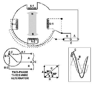
The large schematic in figure 3-7 shows four separate wires brought out from the A and B stator
windings. This is the same as in figure 3-6. Notice, however, that the dotted wire now connects one end of
B1 to one end of A2. The effect of making this connection is to provide a new output voltage. This sine-
wave voltage, C in the picture, is larger than either A or B. It is the result of adding the instantaneous
values of phase A and phase B. For this reason it appears exactly half way between A and B. Therefore, C
must lag A by 45º and lead B by 45º , as shown in the small vector diagram.
Figure 3-7.—Connections of a two-phase, three-wire alternator output.


