3-3
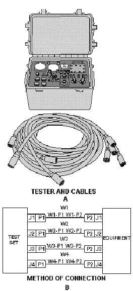
Figure 3-2.—Test equipment cable marking.
View B of figure 3-2 shows the method of connecting the tester to the piece of equipment to be
tested. (For a specific tester, the technical manual supplied with the tester shows the method of
connection.) The tester shown has four cables. These are numbered W1, W2, W3, and W4. Each cable
has two connectors (plugs), one on each end, that are numbered P1 and P2. The cable tag on one end of
the cable reads W1-P1, and the other end reads W1 -P2. As shown in the figure, W1-P1 is connected to
the receptacle J1 on the tester. W1-P2 is then connected to receptacle J1 on the equipment to be tested.
The same procedure is followed for connecting the remaining three cables. The hookup is then complete.
The shipboard and the test equipment cable markings just discussed are only two of many cable-
marking systems you may encounter. There are too many systems to attempt to discuss them all. As stated
earlier, you should study an equipment or installation technical manual before attempting repairs or
connections.


