3-25
Some equipment requires a "warm-up" period between the application of power and some other
action. For example, vacuum tubes (covered later in this training series) require a delay between the
application of filament power and high voltage. A time-delay relay will provide this required delay.
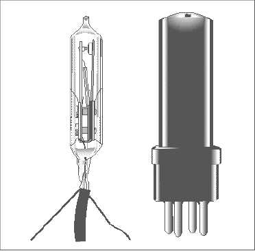
A thermal time-delay relay (fig. 3-23) is constructed to produce a delayed action when energized. Its
operation depends on the thermal action of a bimetallic element similar to that used in a thermal circuit
breaker. A heater is mounted around or near the element. The movable contact is mounted on the element
itself. As the heat causes the element to bend (because of the different thermal expansion rates), the
contacts close.
Figure 3-23.—A thermal time-delay relay.
Relays can be described by the method of packaging; open, semisealed, and sealed. Figure 3-24
shows several different relays and illustrates these three types of packaging.
Figure 3-24 (E), (G) and (H) are open relays. The mechanical motion of the contacts can be observed
and the relays are easily available for maintenance. Figure 3-24 (A), (B) and (C) are semisealed relays.
The covers provide protection from dust, moisture, and other foreign material but can be removed for
maintenance.

