2-23
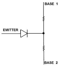
to serve as an excellent oscillator. Testing a UJT is a relatively easy task if you view the UJT as being a
diode connected to the junction of two resistors, as shown in figure 2-15. With an ohmmeter, measure the
resistance between base 1 and base 2; then reverse the ohmmeter leads and take another reading.
Readings should show the same high resistance regardless of meter lead polarity. Connect the negative
lead of the ohmmeter to the emitter of the UJT. Using the positive lead, measure the resistance from the
emitter to base 1 and then from the emitter to base 2. Both readings should indicate high resistances that
are approximately equal to each other. Disconnect the negative lead from the emitter and connect the
positive lead to it. Using the negative lead, measure the resistance from the emitter to base 1 and then
from the emitter to base 2. Both readings should indicate low resistances approximately equal to each
other.
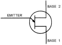
Figure 2-14.—Unijunction transistor.
Figure 2-15.—Unijunction transistor equivalent circuit.
JUNCTION FIELD-EFFECT TRANSISTOR (JFET) TESTS
The junction field-effect transistor (JFET) has circuit applications similar to those of a vacuum tube.
The JFET has a voltage-responsive characteristic with a high input impedance. Two types of JFETs that
you should become familiar with are the junction p-channel and the junction n-channel types, as shown in
figure 2-16. Their equivalent circuits are shown in figures 2-17 and 2-18, respectively. The only
difference in your testing of these two types of JFETs involves the polarity of the meter leads.