3-8
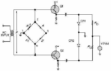
Figure 3-5.—Typical vector-bridge configuration (amplitude).
The absolute value of Z
X
is determined from the dial calibration of R. Without altering the amplitude
balance, you reconnect the external circuits as shown in figure 3-6. Note that the voltage between points 1
and 3 is being compared to the voltage between points 1 and 2. Potentiometer R, calibrated in degrees, is
adjusted for a null indication on the vtvm; and the phase angle is read directly. If Z
X
is purely resistive,
the voltage between points 1 and 3 will be zero and the setting of R will be 0 volts. If ZX is purely reactive
(capacitive or inductive), the setting of R will be at maximum voltage. For phase angles between 0º and
90º, the scale of R may be calibrated directly in degrees. The sign of the phase angle can be determined by
changing the signal frequency slightly and observing the change in impedance. The presence of
harmonics in the signal input will severely hamper the measurements. If a pure frequency source is not
available, suitable low-pass filters will have to be employed in the output leads from the bridge.