2-3
NOTE ON SYMBOLS USED IN THE FOLLOWING SECTIONS: IEEE and ANSI standards (see
inside front cover) are used to define various terms, such as anode (plate) current, anode voltage, and
anode resistance. This book uses Ea for anode voltage, Ia for anode current, and ra for anode resistance.
These are the same as E, Ip, and rp that you will see elsewhere. This module uses the terms anode and plate
interchangeably.
ELECTRON TUBE TESTERS
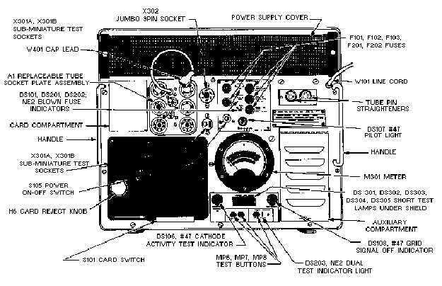
A representative field type of electron tube tester designed to test all common low-power tubes is
shown in figure 2-1. The tube test conditions are as close as possible to actual tube operating conditions
and are programmed on a prepunched card. The card switch (S101, fig. 2-1) automatically programs the
tube test conditions when it is actuated by a card. A card compartment on the front panel of the tester
provides storage for the most frequently used cards. The cover of the tester (not shown) contains the
operating instructions, the brackets for storing the technical manual, the power cord, the calibration cell
for checking the meter and short tests, the calibration cards, the blank cards, and a steel hand punch.
Figure 2-1.—Electron tube tester.
Front Panel
When a prepunched card is fully inserted into the card switch (S101), a microswitch is actuated that
energizes a solenoid, causing the card switch contacts to complete the circuit. The card switch has 187
single-pole, single-throw switches arranged in 17 rows with 11 switches in each row. The card is used to
push the switches closed; thus, the absence of a hole in the card is required to actuate a switch.


