2-36
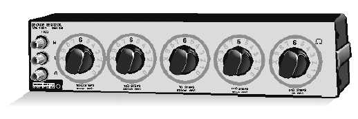
Figure 2-29.—Decade resistor.
DECADE (STEP) ATTENUATORS
Decade attenuators (also referred to as step attenuators) are common devices that may be designed as
either a stand-alone piece of test equipment or as an integral part of an operational piece of electronic
equipment. As the name implies, they are used to attenuate rf signals in incremental steps. Like the fixed
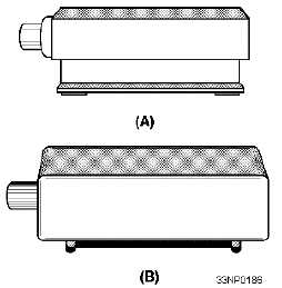
rf attenuator, you can easily test them by using the rf substitution method, as previously described. Views
A and B of figure 2-30 show two types of decade attenuators.
Figure 2-30.—Step attenuators.
50/75-OHM TERMINATIONS
Terminations of 50 and 75 ohms are designed as either feedthrough, impedance-matching devices, or
as rf loading devices. They are precision resistors sealed in small plastic or metal enclosures and are
designed to be mounted on various rf connectors. In the case of feedthrough terminations, they are
designed with rf connectors at both ends, which allows the rf signal to pass through them. They are
impedance-matching devices designed primarily to reduce the voltage standing-wave ratio (vswr) that is
produced when two pieces of equipment with dissimilar impedances are connected together.
You can test a feedthrough termination by measuring the resistance between the center conductor
and the shield of either rf connector with an ohmmeter. As mentioned above, some terminations are
manufactured as loading devices that are designed to shunt an rf signal to ground. A perfectly matched
termination can be compared to a transmitting antenna in that it absorbs all of the rf signal with only a