1-132
Figure 1-42.—Octopus schematic diagram (typical).
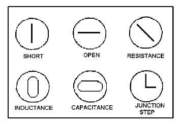
The octopus tests all components for shorts, high resistance, and opens; it checks front-to-back ratios
on junction components (transistors and diodes); and it analyzes ICs and reactive components (capacitors
and inductors). Figure 1-43 shows some typical oscilloscope displays obtained when the octopus is used.
Figures 1-44, 1-45, and 1-46 depict transistor, potentiometer, and combination component displays,
respectively. Detailed operating procedures can be found in topic 6 of NEETS, Module 16, Introduction
to Test Equipment, and in the Electronic Installation and Maintenance Book (EIMB), Test Methods and
Practices, NAVSEA SE000-00-EIM-130.
Figure 1-43.—Typical oscilloscope displays for an octopus.