3-9
Electron deflection in the electromagnetic crt is proportional to the strength of the magnetic fields.
Magnetic field strength depends on current in the coils. The sweep circuits associated with
electromagnetically deflected cathode-ray tubes must provide currents, rather than voltage, to produce the
desired beam deflection.
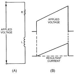
A sawtooth current is required to produce a linear trace. A deflection coil may be considered
equivalent to the circuit shown in view A of figure 3-8. Because of the inductance of the coil, a
trapezoidal voltage must be applied across the coil to produce a sawtooth of current through it. This is
illustrated in view B. (Refer to NEETS, Module 9, Introduction to Wave-Generation and Wave-Shaping
Circuits, for a review of wave shaping.)
Figure 3-8.—Deflection coil equivalent circuit and waveform.
Sweep Rotation
Azimuth indication of the ppi requires that the range trace rotate about the center of the screen. A
very simple means of achieving sweep rotation is to cause the deflection coil to rotate about the neck of
the crt in synchronization with the antenna motion. This method, however, has the disadvantages of
inaccuracy and maintenance complications inherent to any mechanical gear-train assembly.
Most modem ppi systems employ fixed deflection coils and use special circuits to electronically
rotate the magnetic field. Figure 3-9 illustrates a method of electronically producing a rotating sweep. In
view A, a range sweep current, i, is applied to the vertical deflection coils only. The resulting magnetic
field, represented by !, lies along the axis of these coils. The resulting range trace, shown by the short
straight line, is vertical because the electron beam is deflected perpendicular to the magnetic field. In view
B, range sweep currents are applied to both sets of coils, and the resultant magnetic field takes a position
between the axes of the two sets of coils. Because of this shift of the magnetic field, the range trace is
rotated 45 degrees clockwise from its previous position. In view C, the sweep current is applied to the
horizontal deflection coils only, and the range trace lies 90 degrees clockwise from its original position.
Further rotation is obtained if the polarities of the deflection coil currents are varied in proper sequence,
as illustrated in views D and E.