2-28
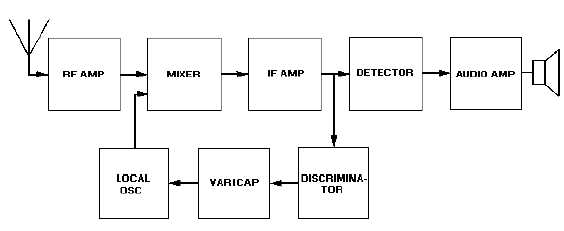
Figure 2-26.—Block diagram of receiver showing automatic frequency control.
The frequency discriminator controls the varicap in this receiver. A varicap is used to keep the IF
stable. You may want to review varicap theory in chapter 3 of NEETS, Module 7, Introduction to Solid-
State Devices and Power Supplies at this point. The varicap application here produces an apparent
reactance, which is included in the oscillator frequency control circuitry. For example, let’s assume the IF
is 455 kilohertz and the local oscillator (lo) is tracking below the incoming station. When the lo output
decreases slightly in frequency, the IF will rise. This causes the output of the discriminator to increase the
capacitive reactance of the varicap, which increases the oscillator frequency to the desired value. Now
let’s assume the lo output increases. The IF will then decrease. This causes the discriminator output to
decrease the capacitive reactance of the varicap. This will cause the oscillator frequency to decrease.
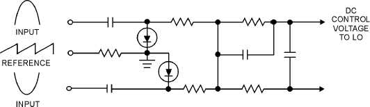
Figure 2-27 shows another widely used type of afc and its circuitry. This type is commonly referred
to as a BALANCED-PHASE DETECTOR or PHASE-DISCRIMINATOR. This circuit uses fixed
capacitors and the varying conductance of the diodes to achieve a variable reactance. As you have seen in
the block diagram, an afc circuit requires two sections, a frequency detector and a variable reactance. Our
detector output is a dc control voltage proportional to the amount of frequency change. This dc voltage is
applied directly to the oscillator. The phase inverter input signals are discriminated IF outputs fed to the
two diodes 180 degrees out of phase.
Figure 2-27.—Automatic frequency control (phase discriminator).
A reference voltage is also applied to both diodes. The diodes are biased to conduct only during the
peak portions of the input signals. Any change in oscillator frequency will alter the phase relationship
between the sawtooth reference voltage and the incoming signals. If this happens, one diode will conduct