6-34
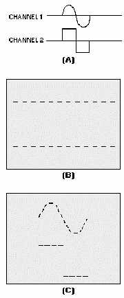
Figure 6-38.—Dual-channel display in CHOP mode.
ADD.—The ADD switch (shown earlier in figure 6-34) algebraically adds the two signals of
channels 1 and 2 together for display.
Other Dual-Trace Oscilloscope Controls
Most dual-trace oscilloscopes have both an A and B time base for horizontal sweep control. Notice
in the upper right corner on our example scope (figure 6-34) the COUPLING, SOURCE LEVEL, and
SLOPE controls. These serve the same function as did those same controls in the A time-base section of
the scope. The B time base is selected using the same A and B TIME/DIV control (pull out outer knob).
The use of the B time base is controlled by the HORIZ DISPLAY section discussed earlier in the A
time-base section. However, inexperienced technicians generally do not use A and B time bases together
in the MIXED, A INTEN (intensified), and B D'LYD (delayed) settings. These controls are fully
explained in the applicable technical manuals; therefore, we will not discuss the controls in this chapter.
Figure 6-39 is a block diagram of a basic dual-trace oscilloscope without the power supplies.