2-7
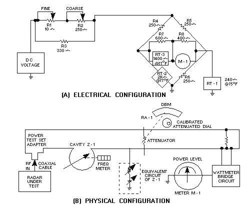
Figure 2-4.—Thermistor bridge.
Before power is applied, R1 and R2 in view A of figure 2-4 are used to adjust the current through
RT-2. When the resistance of RT-2 reaches the equivalent parallel resistance of R6 and RT1 (122.4
ohms), the bridge is balanced. Meter M-1 reads 0 at this time. The rf signal being measured is connected
to the test set and applied via the calibrated attenuator to RT-2. This causes the temperature of RT-2 to
increase, thus reducing its resistance. The bridge becomes unbalanced, causing meter M-1 to deflect an
amount proportional to the decrease in resistance of RT-2. Meter M-1, because of the operation of RT-2,
reads average power.
Q-6. As the dissipated power increases, what effect does this have on the resistance of a thermistor?
If the ambient temperature rises, the resistance of RT-1 decreases. This shunts more current around
the bridge network and allows RT-2 to cool. The resistance of RT-3 decreases, maintaining meter
sensitivity independent of temperature changes. Cavity Z-1 in view B of figure 2-4 is an ABSORPTION-
TYPE FREQUENCY METER. This type of meter will be discussed later.
FREQUENCY MEASUREMENTS
Frequency measurements are an essential part of preventive and corrective maintenance for electric
and electronic equipment. Some examples of the various frequency measurements follow:
Rotation frequencies of some electro-mechanical devices, such as electric motors, must be
determined.