6-31
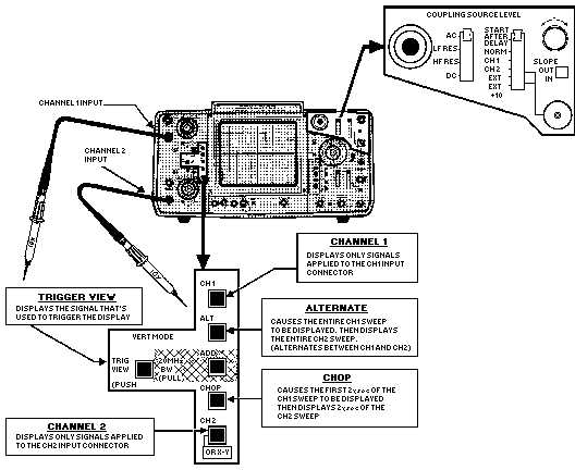
Figure 6-34.—Components to select vertical operating mode.
CH 1 AND CH 2.—These controls allow you to display signals applied to either channel 1 or
channel 2, as discussed earlier.
TRIGGER VIEW.—The TRIG VIEW allows you to display the signal that is actually used to
trigger the display. (Triggering was discussed earlier.)
ALT.—The ALT (alternate) mode (figure 6-35) of obtaining a dual trace uses the techniques of
GATING between sweeps. This control allows the signal applied to channel 1 to be displayed in its
entirety; then, channel 2 is displayed in its entirety. This method of display is continued alternately
between the two channels. At slow speeds, one trace begins to fade while the other channel is being gated.
Consequently, the ALT mode is not used for slow sweep speeds. The CHOP mode, shown in figure 6-36
(explained next), will not produce a satisfactory dual sweep at high speeds. The ALT mode is deficient at
low speeds. Therefore, both are used on dual-trace oscilloscopes to complement each other and give the
scope a more dynamic range of operation.