4-5
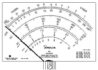
Figure 4-3.—Ohmmeter scale.
Notice that the scale marks are crowded on the left side of the OHMS scale, which makes them
difficult to read. Therefore, the best range to select is one in which the pointer will fall in the space from
midscale to slightly to the right side of midscale. The divisions in this area of the scale are evenly spaced
and provide for easier reading and greater accuracy.
Q-3. When taking resistance readings with a VOM, you will obtain the most accurate readings at or
near what part of the scale?
To explain the relationship between the meter readings and the range switch setting, let’s use an
example. Suppose you have a 2,400-ohm resistor, which you have identified by the resistor color code.
With the range switch in the R 1 position, you connect the meter across the resistor. The meter point
then deflects between 200 and the point labeled with the infinity symbol () on the extreme left side of
the scale. Because the R 1 range is selected, you multiply the reading by 1. Obviously, the scale reading
is not accurate enough. Therefore, you move the range selector switch to the next higher scale position (R
100) to obtain a more easily read value.
In the R 100 position, you again zero the meter. This time, the pointer moves to the 24 mark on the
scale. Because the R 100 scale is selected, the reading is multiplied by 100. This gives a more accurate
reading of 2,400 ohms (24 times 100).
If you position the range switch to the R 10,000 scale, accuracy decreases. The most accurate
readings are obtained at or near midscale. Other VOM instruments have ranges with other settings, such
as R 10, R 100, or R 1,000, to make it easier to make such readings.
Another thing to remember when you are measuring resistance is the tolerance of the resistor. If the
tolerance of the resistor in the preceding example is 10 percent, we would expect a reading between
approximately 2,160 and 2,640 ohms. If the reading is not within these limits, the resistor has probably
changed value and should be discarded.
An open resistor will indicate no deflection on the meter. A shorted resistor causes full-scale
deflection to the right on the lowest range scale, such as if the leads were shorted together.