3-13
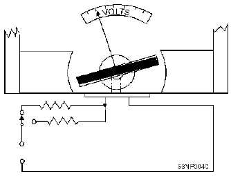
card frame. For high-voltage ranges, the series resistance can be connected externally. A simplified
diagram of a voltmeter is shown in figure 3-8.
Figure 3-8.—Internal construction and circuit of a simplified voltmeter.
Q-15. What modification is made to the D’Arsonval meter movement to enable the meter to measure
voltage?
Keep in mind that the D’Arsonval meter movement uses current flow to produce a magnetic field that
is proportional to the current. The meter movement is, therefore, an indicator of current flow rather than
voltage. The addition of the series resistance is what allows the meter to be calibrated in terms of voltage;
that is, the meter movement of a voltmeter operates because of the current flow through the meter, but the
scale is marked in volts. For example, the meter movement shown in figure 3-9 has an internal resistance
of 100 ohms, requires 100 microamperes for full-scale deflection, and has a voltage drop of 10 millivolts
when full-scale deflection is reached. If you were to place this meter directly across a 10-volt source, an
excessive current (in milliamperes) would flow. The meter would be destroyed because of the excessive
current flowing through the meter movement. This can be seen in the following Ohm’s law application:
Figure 3-9.—Use of multiplier resistors with D'Arsonval meter movement.
Using this equation, you can see that a current through the meter of 100 milliamperes is excessive
and will cause damage.