1-26
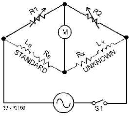
Figure 1-8.—Inductance bridge.
The ac signal is applied to the bridge, and variable resistors R1 and R2 are adjusted for a minimum
or zero deflection of the meter, indicating a condition of balance. When the bridge is balanced, the
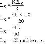
following formulas may be used to find Lx.
(NOTE: The right side of this expression is NOT inverse as it was in the capacitance bridge.)
and
or
In figure 1-8, for example, the values of R1, R2, and Rs are 20, 40, and 60 ohms, respectively. The
value of Ls is 10 millihenries. We can find the values of Rx and Lx by using their respective formulas as
follows: