6-11
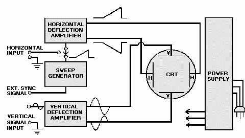
divided into the basic sections shown in figure 6-13: (1) a CRT, (2) a group of control circuits that control
the waveform fed to the CRT, (3) a power supply, (4) sweep circuitry, and (5) deflection circuitry.
Figure 6-13.—Block diagram of an oscilloscope.
Q-14. List the circuits that all oscilloscopes have in common.
Figure 6-14 is a drawing of the front panel of a dual-trace, general-purpose oscilloscope.
Oscilloscopes vary greatly in the number of controls and connectors. Usually, the more controls and
connectors, the more versatile the instrument. Regardless of the number, all oscilloscopes have similar
controls and connectors. Once you learn the fundamental operation of these common controls, you can
move with relative ease from one model of oscilloscope to another. Occasionally, controls that serve
similar functions will be labeled differently from one model to another. However, you will find that most
controls are logically grouped and that their names usually indicate their function.


