1-30
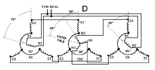
Figure 1-20D.—TX-TDX-TR system operation (subtraction).
Up to this point, we have discussed the number of degrees a rotor is turned. Now, it is important to
point out the labeling of synchro positions. Labeling is necessary to determine the actual position of the
synchro's rotor. Notice that synchro rotor positions are labeled from 0º, increasing in a counterclockwise
direction. It is common practice to refer to a synchro transmitter as being on 120º when its rotor is
pointing toward the S3 winding. Do not confuse these positions with the number of degrees a rotor is
turned.
Assume that a 240º input is applied to the system, as indicated in view B, by turning the TX rotor to
its 240º position. At this position maximum voltage is induced into the S1 winding of the TX and coupled
to S1 of the TDX. Since the TDX rotor is on 0º, it passes this maximum voltage (via R1) along to the S1
winding of the TR. The stator magnetic field in the receiver now lines up in the direction of the S1
winding and causes the rotor to turn counterclockwise to the 240º position. This illustrates an important
point:
Whenever the TDX rotor is at 0º, the TR rotor follows the TX rotor exactly. In the present case, the
system has just solved the equation 240º
-
0º = 240º.
Before we go to another example, you need to understand that when you subtract a higher value of
degrees from a lower value of degrees, you add 360º to the lower value and subtract directly.
For example: 10º - 260º
Add 360º to lower value: 10º + 360º = 370º
Subtract: 370º
-
260º = 110º
In the next example, hold the TX rotor on 0º and turn the TDX rotor to 120º, as illustrated in view C
of figure 1-20. In this situation, R1 of the TDX has maximum voltage induced in its winding since it is in
line with S2. With R1 of the TDX connected to S1 of the TR, the TR stator magnetic field lines up in the
direction of S1 and causes the TR rotor to turn clockwise to the 240º position. Given, then, that the TX is
on 360º (or the 0º position), and subtracting the 120º displacement of the TDX rotor, the difference is
240º. This is the position at which the TR rotor comes to rest. Therefore, the system has solved the
equation 360º
-
120º = 240º. The actual subtraction operation of the TDX is a little more apparent in the
next example.