1-41
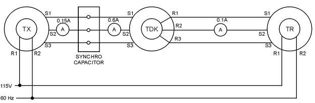
Figure 1-31.—The use of a synchro capacitor with a TDX.
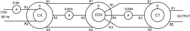
Some synchro systems contain a differential and a control transformer, as illustrated in figure 1-32.
In this figure, there are large stator currents flowing in the CX, since it supplies all the losses as well as
the magnetizing current for both synchros. Two meters are placed in the circuit to show the value of stator
current for the CDX and CT. Another meter is placed in series with the ac excitation voltage to show the
amount of current being drawn from the ac line is 0.9 ampere.
Figure 1-32.—Synchro current in a control synchro system using a CDX and a CT.
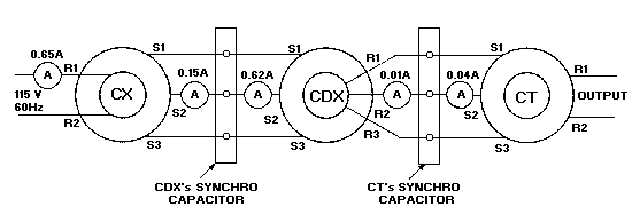
Adding synchro capacitors to this system, as shown in figure 1-33, greatly reduces the stator currents
and improves the efficiency of the system. Also, notice that the line current is reduced from 0.9 ampere in
figure 1-32 to 0.65 ampere in figure 1-33.
Figure 1-33.—The effects of synchro capacitors in a control synchro system using a CDX and a CT.