1-36
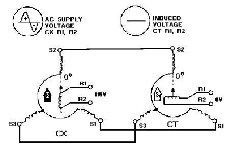
Figure 1-25.—CX-CT system operation with rotor in correspondence.
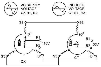
When the CT rotor is rotated 90º, as shown in figure 1-26, the rotor is parallel to the resultant stator
field Maximum magnetic coupling occurs between the rotor and stator fields at this point. As a result of
this coupling, the stator windings induce a maximum of 55 volts into the rotor winding. The phase of this
voltage depends upon the direction in which the CT rotor is turned. The rotor of the CT is wound so that
clockwise rotation of the stator magnetic field induces a voltage across the rotor which is proportional to
the amount of rotation and in phase with the ac supply voltage. Counterclockwise rotation of the stator
magnetic field produces a voltage that is still proportional to the amount of rotation, but 180º out of phase
with the supply voltage. Keep in mind that the clockwise rotation of the CT stator magnetic field is the
same as the counterclockwise rotation of the CT rotor. This phase relationship between the ac supply
voltage and the CT output voltage becomes more apparent in figure 1-27.
Figure 1-26.—CX-CT system operation with the CX rotor at 0º and the CT rotor at 90º.