• Home
  • Download PDF
  • Order CD-ROM
  • Order in Print
AMPLITUDE-MODULATED SYSTEMS
Figure 1-22A.Essential elements of ON-OFF keying.

Neets Module 12-Modulation Principles
Page Navigation
  22    23    24    25    26  27  28    29    30    31    32  
1-27 
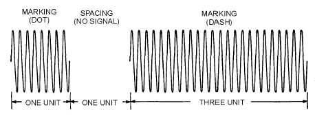
during which signal is present is called the MARKING interval, and the period of no signal is called the SPACING interval. Figure 1-22 shows the relationships between the rf carrier view (A), the on-off keying waveform view (B), and the resultant carrier wave view (C). 
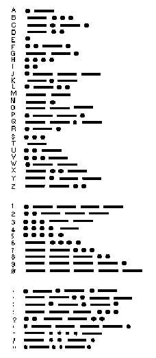
Figure 1-20.—International Morse code. Figure 1-21.—Dot and dash in radiotelegraph code.


Western Governors University

Privacy Statement
Press Release
Contact

© Copyright Integrated Publishing, Inc.. All Rights Reserved. Design by Strategico.