2-35
earlier). Notice that electron Q1 is moving against the ac field around cavity A. The electron takes energy
from the ac field and then accelerates, turning more sharply when its velocity increases. Thus, electron Q1
turns back toward the cathode. When it strikes the cathode, it gives up the energy it received from the ac
field. This bombardment also forces more electrons to leave the cathode and accelerate toward the anode.
Electron Q2 is slowed down by the field around cavity B and gives up some of its energy to the ac field.
Since electron Q2 loses velocity, the deflective force exerted by the H field is reduced. The electron path
then deviates to the left in the direction of the anode, rather than returning to the cathode as did electron
Q1.
The cathode to anode potential and the magnetic field strength determine the amount of time for
electron Q2 to travel from a position in front of cavity B to a position in front of cavity C. Cavity C is
equal to approximately 1/2 cycle of the rf oscillations of the cavities. When electron Q2 reaches a position
in front of cavity C, the ac field of cavity C is reversed from that shown. Therefore, electron Q2 gives up
energy to the ac field of cavity C and slows down even more. Electron Q2 actually gives up energy to
each cavity as it passes and eventually reaches the anode when its energy is expended. Thus, electron Q2
has helped sustain oscillations because it has taken energy from the dc field and given it to the ac field.
Electron Q1, which took energy from the ac field around cavity A, did little harm because it immediately
returned to the cathode.
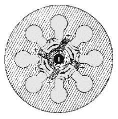
The cumulative action of many electrons returning to the cathode while others are moving toward the
anode forms a pattern resembling the moving spokes of a wheel known as a SPACE-CHARGE WHEEL,
as indicated in figure 2-33. Electrons in the spokes of the wheel are the working electrons.
The space-charge wheel rotates about the cathode at an angular velocity of 2 poles (anode segments)
per cycle of the ac field. This phase relationship enables the concentration of electrons to continuously
deliver energy to sustain the rf oscillations. Electrons emitted from the area of the cathode between the
spokes are quickly returned to the cathode.
In figure 2-33 the alternate segments between cavities are assumed to be at the same potential at the
same instant. An ac field is assumed to exist across each individual cavity. This mode of operation is
called the PI MODE, since adjacent segments of the anode have a phase difference of 180 degrees, or
one-pi radian. Several other modes of oscillation are possible, but a magnetron operating in the pi mode
has greater power and output and is the most commonly used.
Figure 2-33.—Rotating space-charge wheel in an eight-cavity magnetron.