1-42
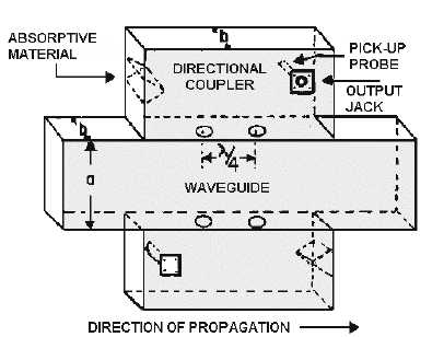
Figure 1-53.—Directional coupler.
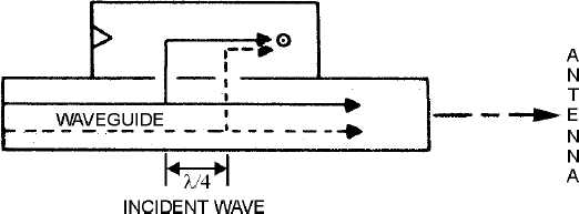
Figure 1-54 illustrates two portions of the incident wavefront in a waveguide. The waves travel down
the waveguide in the direction indicated and enter the coupler section through both holes. Since both
portions of the wave travel the same distance, they are in phase when they arrive at the pickup probe.
Because the waves are in phase, they add together and provide a sample of the energy traveling down the
waveguide. The sample taken is only a small portion of the energy that is traveling down the waveguide.
The magnitude of the sample, however, is proportional to the magnitude of the energy in the waveguide.
The absorbent material is designed to ensure that the ratio between the sample energy and the energy in
the waveguide is constant. Otherwise the sample would contain no useful information.
Figure 1-54.—Incident wave in a directional coupler designed to sample incident waves.
The ratio is usually stamped on the coupler in the form of an attenuation factor.
The effect of a directional coupler on any reflected energy is illustrated in figure 1-55. Note that
these two waves do not travel the same distance to the pickup probe. The wave represented by the dotted
line travels 1/2! further and arrives at the probe 180 degrees out of phase with the wave represented by