3-2
The effectiveness of an entire transmitting/ receiving system depends largely on impedance matching
between the elements of the system. Impedance matching is particularly critical at the antenna connection.
If a good impedance match is maintained between the system and the antenna throughout the operating
frequency band, power transfer to and from the antenna is always maximum. The transmission line or
waveguide used to transport energy to and from the antenna should have a characteristic impedance equal
to that of the antenna. A proper impedance match allows all available power to be absorbed and radiated
by the antenna without reflections back down the line.
If you have a transmission line or waveguide with an impedance mismatch at the termination,
standing waves are set up by the reflections. Standing waves cause losses in the form of unwanted
radiations, heat losses in transmission lines, and arcing in waveguides.
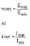
The STANDING-WAVE RATIO, abbreviated swr, is a way to measure the degree of mismatch
between the transmission line and its load. The swr can be expressed as a ratio of the maximum and
minimum values of the current or voltage in the standing waves that are set up on the lines as follows:
A transmission line or waveguide approaches a perfectly matched condition when the swr
approaches a value of 1. A ratio that is a little higher than 1 is usually acceptable in practical applications.
Measurement of swr is the only practical method of detecting an impedance mismatch between a
transmitting/receiving system and its antenna. As such, the system swr is an important indication of the
overall efficiency of the system during operation.
The line impedance can usually be matched to the antenna at only one frequency. However, the swr
will NOT become too high if the antenna is used over a small range of frequencies and the line is matched
to the center frequency.
Antenna Directivity
You can divide antennas into two general classes based on directivity, omnidirectional and
directional. OMNIDIRECTIONAL antennas radiate and receive energy from all directions at once
(SPHERICAL WAVEFRONT). They are seldom used in modern radar systems as the primary antenna,
but are commonly used in radio equipment and iff (identification friend or foe) receivers.
DIRECTIONAL antennas radiate energy in LOBES (or BEAMS) that extend outward from the antenna in
either one or two directions. The radiation pattern contains small minor lobes, but these lobes are weak
and normally have little effect on the main radiation pattern. Directional antennas also receive energy
efficiently from only one or two directions, depending upon whether it is unidirectional or bidirectional.
Directional antennas have two characteristics that are important to you in radar and communications
systems. One is DIRECTIVITY and the other is POWER GAIN. The directivity of an antenna refers to
the NARROWNESS of the radiated beam. If the beam is NARROW in either the horizontal or vertical
plane, the antenna has a high degree of directivity in that plane. An antenna may be designed for high
directivity in one plane only or in both planes, depending on the application. The power gain of an