2-15
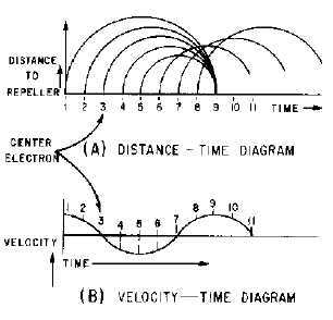
Figure 2-10.—Electron bunching diagram.
The variation in grid voltage causes the electrons to enter the space between the grid and the repeller
at various velocities. For example, in figure 2-10, views (A) and (B), the electrons at times 1 and 2 are
speeded up as they pass through the grid. At time 3, the field is passing through zero and the electron is
unaffected. At times 4 and 5, the grid field is reversed; the electrons give up energy because their velocity
is reduced as they pass through the grids.
The distance the electrons travel in the space separating the grid and the repeller depends upon their
velocity. Those moving at slower velocities, such as the electron at time 4, move only a short distance
from the grid before being affected by the repeller voltage. When this happens, the electron is forced by
the repeller voltage to stop, reverse direction, and return toward the grid. The electrons moving at higher
velocities travel further beyond the grid before reversing direction because they have greater momentum.
If the repeller voltage is set at the correct value, the electrons will form a bunch around the constant-speed
electrons. The electrons will then return to the grid gap at the instant the electrostatic field is at the correct
polarity to cause maximum deceleration of the bunch. This action is also illustrated in figure 2-10, view
(A). When the grid field provides maximum deceleration, the returning electrons release maximum
energy to the grid field which is in phase with cavity current. Thus, the returning electrons supply the
regenerative feedback required to maintain cavity oscillations.
The constant-speed electrons must remain in the reflecting field space for a minimum time of 3/4
cycle of the grid field for maximum energy transfer. The period of time the electrons remain in the
repeller field is determined by the amount of negative repeller voltage. The reflex klystron will continue
to oscillate if the electrons remain in the repeller field longer than 3/4 cycle (as long as the electrons
return to the grid gap when the field is of the proper polarity to decelerate the electrons). Figure 2-11
shows the effect of the repeller field on the electron bunch for 3/4 cycle and for 1 3/4 cycles. Although
not shown in the figure, the constant-velocity electrons may remain in the repeller field for any number of
cycles over the minimum 3/4 cycle. If the electrons remain in the field for longer than 3/4 cycle, the
difference in electron transit time causes the tube performance characteristics to change. The differences
in operating characteristics are identified by MODES OF OPERATION.