1-55
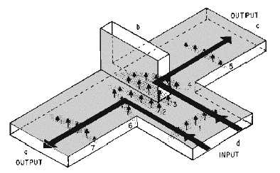
Figure 1-68.—Magic-T with input to arm d.
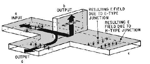
When an input signal is fed into the a arm as shown in figure 1-69, a portion of the energy is coupled
into the b arm as it would be in an E-type T junction. An equal portion of the signal is coupled through
the d arm because of the action of the H-type junction. The c arm has two fields across it that are out of
phase with each other. Therefore the fields cancel, resulting in no output at the c arm. The reverse of this
action takes place if a signal is fed into the c arm, resulting in outputs at the b and d arms and no output at
the a arm.
Figure 1-69.—Magic-T with input to arm a.
Unfortunately, when a signal is applied to any arm of a magic-T, the flow of energy in the output
arms is affected by reflections. Reflections are caused by impedance mismatching at the junctions. These
reflections are the cause of the two major disadvantages of' the magic-T. First, the reflections represent a
power loss since all the energy fed into the junction does not reach the load which the arms feed. Second,
the reflections produce standing waves that can result in internal arching. Thus the maximum power a
magic-T can handle is greatly reduced.
Reflections can be reduced by using some means of' impedance matching that does not destroy the
shape of' the junctions. One method is shown in figure 1-70. A post is used to match the H plane, and an
iris is used to match the E plane. Even though this method reduces reflections, it lowers the power-
handling capability even further.