4-34
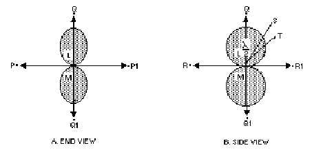
Figure 4-29.—Parallel elements 180 degrees out of phase.
Consider what happens along the QQ1 axis. Energy radiating from element M toward Q reaches
element L in about 1/2 cycle (180 degrees) after it leaves its source. Since element L was fed 180 degrees
out of phase with element M, the wavefronts are now in the same phase and are both moving toward Q
reinforcing each other. Similar reinforcement occurs along the same axis toward Q1. This simultaneous
movement towards Q and Q1 develops a bi-directional pattern. This is not always true in end-fire
operation. Another application of the end-fire principle is one in which the elements are spaced 1/4
wavelength apart and phased 90 degrees from each other to produce a unidirectional pattern.
In figure 4-29, view A, elements A and B are perpendicular to the plane represented by the page;
therefore, only the ends of the antennas appear. In view B the antennas are rotated a quarter of a circle in
space around the QQ1 axis so that they are seen in the plane of the elements themselves. Therefore, the
PP1 axis, now perpendicular to the page, is not seen as a line. The RR1 axis, now seen as a line, is
perpendicular to the PP1 axis as well as to the QQ1 axis. The end-fire array is directional in this plane
also, although not quite as sharply. The reason for the greater broadness of the lobes can be seen by
following the path of energy radiating from the midpoint of element B toward point S in view B. This
energy passes the A element at one end after traveling slightly more than the perpendicular distance
between the dipoles. Energy, therefore, does not combine in exact phase toward point S. Although
maximum radiation cannot take place in this direction, energy from the two sources combines closely
enough in phase to produce considerable reinforcement. A similar situation exists for wavefronts traveling
toward T. However, the wider angle from Q to T produces a greater phase difference and results in a
decrease in the strength of the combined wave.
Directivity occurs from either one or both ends of the end-fire array, along the axis of the array, as
shown by the broken arrows in figure 4-28, view A; hence, the term end-fire is used.
The major lobe or lobes occur along the axis of the array. The pattern is sharper in the plane that is at
right angles to the plane containing the elements (figure 4-29, view A). If the elements are not exact
half-wave dipoles, operation is not significantly affected. However, because of the required balance of
phase relationships and critical feeding, the array must be symmetrical. Folded dipoles, such as the one
shown in figure 4-20, view A, are used frequently because the impedance at their terminals is higher. This
is an effective way of avoiding excessive antenna losses. Another expedient to reduce losses is the use of
tubular elements of wide diameter.
GAIN AND DIRECTIVITY.—In end-fire arrays, directivity increases with the addition of more
elements and with spacings approaching the optimum. The directive pattern for a two-element,