4-20
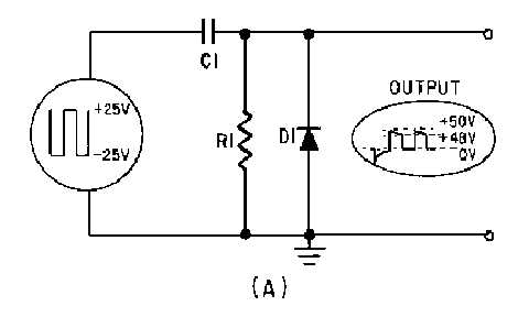
Figure 4-18A.—Positive damper and waveform.
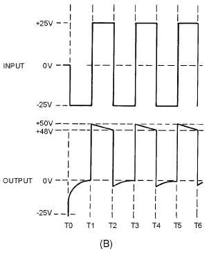
Figure 4-18B.—Positive damper and waveform.
At T0 the
-
25 volt input signal appears across R1 and D1 (the capacitor is a short at the first instant).
The initial voltage across R1 and D1 causes a voltage spike in the output. Because the charge time of C1
through D1 is almost instantaneous, the duration of the pulse is so short that it has only a negligible effect
on the output. The
-
25 volts across D1 makes the cathode negative with respect to the anode and the
diode conducts heavily. C1 quickly charges through the small resistance of D1. As the voltage across C1
increases, the output voltage decreases at the same rate. The voltage across C1 reaches -25 volts and the
output is at 0 volts.