1-38
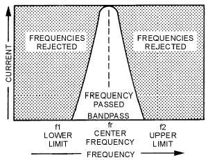
Figure 1-19.—Bandpass filter response curve.
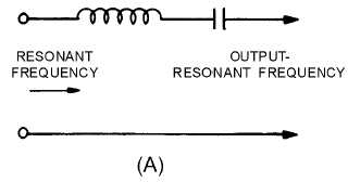
In the circuit of figure 1-20, view (A), the series-LC circuit replaces the inductor of figure 1-16, view
(A), and acts as a BANDPASS filter. It passes currents having frequencies at or near its resonant
frequency, and opposes the passage of all currents having frequencies outside this band.
Figure 1-20A.—Components of a simple bandpass filter.
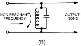
Thus, in the circuit of figure 1-20, view (B), the parallel-LC circuit replaces the capacitor of figure 1-
16, view (B). If this circuit is tuned to the same frequency as the series-LC circuit, it will provide a path
for all currents having frequencies outside the limits of the frequency band passed by the series-resonant
circuit. The simplest type of bandpass filter is formed by connecting the two LC circuits as shown in
figure 1-20, view (C). The upper and lower frequency limits of the filter action are filter cutoff points.
Figure 1-20B.—Components of a simple bandpass filter.